
Research and production company Grasys is an expert in membrane gas separation; we have been manufacturing equipment based on membrane technology since the year 2001. Our profound experience in designing membrane equipment and expertise in technology ensures that the Customer will arrive at the most cost-effective result while enjoying individual approach to resolving gas separation challenges. The state-of-the-art gas separation membrane is far from a flat plate or film but a hollow fiber.
A cutting-edge hollow fiber membrane is comprised of a porous polymer fiber with gas separation layer on its outer surface is used for membrane gas separation technologies. The porous fiber is of a complex asymmetric structure, the polymer density increases as it approaches the fiber outer surface. The use of porous substrates with asymmetric structure enables to separate gases at high pressure.
.jpg)
.jpg)
.jpg)
The fiber gas separation layer thickness is no higher than 0.1 μm, which provides gases with high specific permeability through the polymer membrane. The current level of technology development enables to manufacture polymers of high selectivity when separating various gases, which ensures gaseous products of high purity, accordingly. A cutting-edge membrane module used in membrane gas separation technology is comprised of a replaceable membrane cartridge and a body. The fiber packing density in cartridge reaches 3000–3500 square meters of fiber per cubic meter of the cartridge, which makes it possible to keep the gas separation unit size to a minimum.
Airflow Distribution Pattern in Grasys Membrane Module *
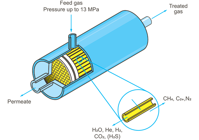
*Airflow distribution pattern in Grasys membrane module with external gas supply. In some applications internal gas supply modules can be used as well.
The module body has one connection pipe for feed gas mixture inlet and two connection pipes for separated components outlet.
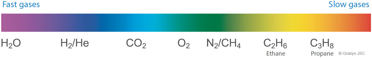
Mixture separation using membrane technology is accounted for the partial pressure difference on the hollow fiber membrane outer and inner surfaces. Gases that penetrate polymer membrane fast (such as H2, CO2, O2, water vapor, higher hydrocarbons) come into the fiber and come out of membrane cartridge through one of the outlet connection pipes. Gases that penetrate membrane slowly (such as CO, N2, CH4), come out of membrane module through the second outlet connection pipe.
Hollow Fiber Membranes of Own Making.
The First in Russia Gas Separation Membrane Cartridge Plant
In the city of Dubna (Moscow region) Grasys has started the first in Russia and the CIS production of hollow fiber gas separation membranes and membrane cartridges with a broad application scope in various industries, including oil and gas, metallurgy, food and many others.
This is one-of-a-kind research and production complex located within the Dubna Technology and Innovation Special Economic Zone. One of the high-profile business lines covers manufacture of membrane cartridges to separate hydrocarbon gases, as well as to recover helium concentrate.
Membrane cartridges manufactured by Grasys are used to reduce or concentrate helium, carbon dioxide in natural gas, as well as to dry natural gas, reduce hydrogen sulfide content, concentrate hydrogen in HBG processing problems.
Thus, the use of membranes to recover helium from natural gas will be instrumental in substantial reduction of energy costs for the gas treatment during production, processing and transportation. Gas and oil companies will be able to sell helium separated by this technology as a separate product. Helium enjoys a high demand in the metallurgical, food and electrical industries.
One of the first users of gas separation membranes are companies producing hydrocarbons in the fields of Eastern Siberia and the Far East. In particular, by applying such membranes, Gazprom is engaged in helium recovery at the Chayanda oil and gas condensate field, Yakutia, which is the resource base of the Power of Siberia gas pipeline, for further delivery to the Amur gas processing plant.
This project is being implemented under an agreement signed with the Ministry for Investments and Innovations of the Moscow Region and JSC “SEZ TVT Dubna”, with financial support from the Industrial Development Fund.

.jpg)
.jpg)